From airframe-specific Health Usage and Management Systems (HUMS) to portable rotor track and balancing units, there are a lot of advanced technology tools available to help keep helicopters flying smoother, safer and more efficiently.
Unlike the pampered “keep the passenger happy” lives enjoyed by the typical corporate or commercial aircraft, the average helicopter has to work really hard to earn its keep.
And that means the airframe is subject to the ongoing affects caused by a lot of internal and external vibration.
And minimizing that vibration can go a long way to helping to keep the crew, passengers and airframe as healthy and happy as possible. But, before you can locate and mitigate the vibration, you first need to understand the various types you are dealing with.
“Not all vibration is the same or even comes from the same elements,” stated Todd Underwood, Aviation Produce support specialist, ACES Systems.
“To properly analyze a helicopter’s vibrations, you have to know and understand the differences between the major types of vibration.”
Vibration: When a rigid or elastic body is forcibly moved from a position or state of equilibrium, that force create motion we know as vibration, which can be oscillating, reciprocating, periodic, random or harmonic.
Flutter: Flutter is caused when unsteady aerodynamics excites the naturally occurring frequencies of an aircraft as the air flows over it. Because it can quickly grow in magnitude that can cause structures to fail, flutter is extremely dangerous to an aircraft. A similar problem occurs in brides and was the cause of the collapse of the Tacoma Narrows Bridge in 1940.
Buffet: Buffet is what most every pilot relates to flying in turbulent conditions. It is typically felt as random vibration caused by aerodynamic loads – lowering flaps or landing gear – or atmospheric thermals.
Noise: Any noise you hear is simply a pressure wave of air being driven by a vibrating component. But in extreme situations, that unchecked harmonic imbalance can lead to structural fatigue, damage and even failure.
“In an aircraft or its engine, when a component’s job is to rotate, it’s going to generate a measurable amount of vibration and/or noise as a result of that motion,” Underwood said. “Helicopter rotors are certainly no exception. Even though some vibration is normal, a damaged, worn or improperly balanced rotor will create excessive vibration levels, which can fatigue the flight crew and shorten the service life of the rotor and other parts of the assembly.”
Whether it’s flying or fixing; every element of a helicopter’s operation and maintenance is elegantly complex. And thankfully, as with many aspects of our industry, there are a number of technologies that can help optimize and simplify the inspection and repair of key components.
With regards to vibration isolation and mitigation, two of the major advancements are helicopter airframe health and usage monitoring systems (HUMS) and portable, digital rotor track and balancing units.
Healthy Helicopter = Happy Maintainer
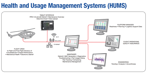
In its simplest form, a HUMS installation is comprised of a series of strategically-placed airframe sensors and other ancillary systems, including sophisticated aircraft specific algorithms that can provide ongoing information pertaining to the condition of the aircraft’s key components and systems.
As Kevin Hawko, manager of Vehicle Health Business Development for Collins Aerospace explained it, “The HUMS monitors aircraft system performance characteristics via a sensor network and compares the measurements to thresholds that are determined during the design of the system. Fully integrated HUMS will communicate with the aircraft avionics data bus and can correlate measurements with engine performance and aircraft operating parameters (airspeed, altitude, attitude, rate of turn, etc.…). The fully correlated data is stored for off board analysis, he said.
“Traditional Health Usage and Management Systems are a combination of sensors and software algorithms that monitor the performance of equipment and drivetrains on aircraft and compares sensor measurements to thresholds to determine when equipment health is degrading, operating limits are exceeded and can be used to troubleshoot and diagnose failures,” he said. “With advanced HUMS like our Pulse system, the equipment can determine aircraft flight regimes and automatically trigger data acquisitions for functions like rotor and shaft balance or engine performance checks. When integrated with a ground-based management environment, HUMS can also be used to perform trend analysis on a specific aircraft or an operator’s fleet.” Hawko said that the HUMS technology would collect and distribute data on a number of critical helicopter systems including:
- Engine and Rotor System operating times
- Drivetrain vibration monitoring with condition/health indicators for drive train components (bearings, couplings, gears & shafts)
- Rotor system track and balancing with recommended smoothing adjustments
- Engine performance and automated power assurance checks
- Aircraft operating limit excedances including speed, torque, power, angle of bank and engine pressure/temperatures
- Aircraft flight regimes (climbs/descents, angle of bank, rate of turn, altitude, airspeed)
- Cockpit voice/flight data
- Aircraft system or airframe sensing, including strain, pressure, temp, speed, and vibration.
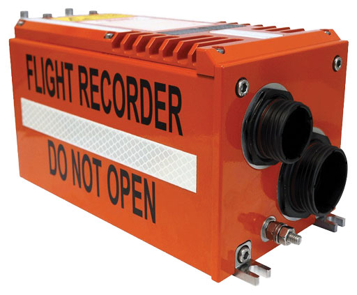
Curtiss-Wright Defense Solutions Has FDR/HUMS Combo
Curtiss-Wright Defense Solutions has recently created a unique rotorcraft HUMS solution by integrating a data acquisition system designed for HUMS into its recently ETSO qualified Fortress crash protected flight data recorder (FDR). Curtiss-Wright says it has been manufacturing recorders since 1957 and touts they were the first to obtain RTCA-DO178 approval for their solid state recorders.
Fortress HUMS provides the benefits of having an FDR and a fully functioning HUMS without requiring two separate boxes. By combining the systems, weight can drop significantly versus currently available systems (up to 50 lb (22 kg) possible). At the same time, commonality reduces the space and power required.
Better Info = Savings
“It’s all about enabling operators to diagnose and perform maintenance on condition, rather than on schedule or unplanned, coupled with the ability to predict remaining useful life of components, which can lend significant efficiencies when troubleshooting, diagnosing and correcting an issue,” he said. “The Pulse system’s design assurance levels offer the ability to use HUMS data for maintenance credit, and is ideal for monitoring aircraft subsystems and drive trains, accessing organic sensor data or new, lightweight digital sensors that can be added to monitor targeted systems.”
Hawko also stated that by monitoring that spectrum of data, the HUMS provides operators with a number of services, including automated power assurance checks, reducing maintenance test flights and increasing aircraft operational availability, In-flight crew alerts when thresholds are exceeded, drivetrain and engine health assessments, and automated logbook entries for maintenance records.
“In this way, operators can benefit from actionable alerts for maintenance organizations while an aircraft is still in flight so that when an aircraft arrives at an airport, quick visual displays on mobile devices will aid in assessing health and status of the aircraft,” he said. “They also benefit from the integration of parts tracking databases, maintenance action information systems and parts catalogs to help operators track components’ time on wing and the service history from manufacture through MRO systems, as well as benefiting from links to central maintenance systems to help automate just-in-time ordering of parts to align with scheduled maintenance periods at designated locations.”
“This approach will allow operators to optimize parts inventories and maximize the utilization of equipment,” Hawko said. “Bottom line; these systems help improve aircraft readiness, reduce operating and maintenance costs and improved the overall safety of aircraft.”
While a new-generation HUMS system provides a tremendous amount of information to helicopter operators and maintainers, the physical size, weight and cost of these system still make them impractical for most midsize and light helicopters.
“While largely adopted by military and commercial offshore rotorcraft operators, HUMS is still largely a “nice to have” for commercial helicopter operators,” he said. “Improvements in processing capabilities and more digital aircraft avionics suites help to make HUMS more feasible in the lighter civil sector. In addition, newer sensing system and software architectures lessen the certification impacts and modern package sizing for both the HUMS processor and the sensing system helps solve the weight issues.”
“Our industry is also working to make wireless sensing a reality, further reducing system weight and installation times,” Hawko added.
Stopping Vibration in its Rotor Tracks
Obviously, the major contributor of vibration on a helicopter is its main rotor assembly. That’s a lot of mass swinging around up there. And while it leaves the factory as a balanced assembly, it doesn’t take long before centrifugal and environmental forces take their toll.
Underwood explained that helicopter blades are manufactured as perfectly balanced, matched sets and should theoretically operate smoothly throughout their lifespan. But that’s not how it works in the real world. Over time and through a variety of situations, they can erode, wear down or sustain minor damage – all of which will cause the set to become unbalanced.
That’s when increased vibration sets in.
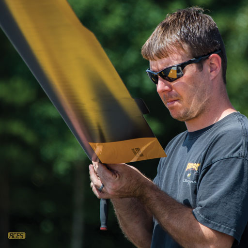
The first line of defense in mitigating rotor vibration is through a process called rotor blade tracking and balancing. Historically, this type of maintenance would often send helicopter mechanics in search of a new career.
“There are two types of vibration that are typically measured when performing a track and balance inspection: vertical and lateral,” he said. “Vertical vibration is often the result of the rotor blades’ inability to provide equal lift. Lateral vibration is caused by unbalanced mass distribution and/or a misalignment of the rotor system.”
Back some 40-plus years ago when I first learned to fly helicopters in a Bell 47, our mechanic’s technique for balancing included a glass of water set on the floorboard – really. That’s an extreme case, but typical manual rotor balancing practices aren’t much easier or more accurate.
“When you refer to the helicopter’s maintenance manual it’s going to tell you that if you adjust the barrel of the pitch link one turn it will result in a certain amount of pitch change with the blade,” Underwood explained. “That adjustment information is found on a polar chart. But that chart doesn’t tell you that the resulting change will be different on the ground, in hover and cruising at 100-knots – which it will. The results will be different for every aircraft and flight condition.”
“The process is typically to make the adjustments per the chart and run the aircraft to see what effect it has,” he said. “It’s a lot of trial and error and it requires repeated engine runs.”
Thankfully for helicopter mechanics and owners there are new technology tools that not only greatly improve the accuracy of rotor balancing, but also greatly reduce the number of runs required.
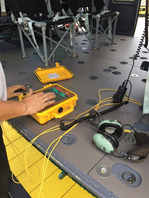
“ACES Systems’ new digital track and balance analyzers utilize stored coefficient of influence in conjunction with a ‘learning algorithm,’ which allows the unit to become smarter with each successful track and balance run,” Chris Mullins, executive vice president of Marketing and Product Support for ACES Systems said. “There is some intelligence in the unit that helps the technician make adjustments in weight, pitch links and tabs relative to the run-to-run responses of the helicopter being balanced.”
“The learning capability makes those adjustments much more accurate than those provided on a polar chart, which is a ‘ball park’ estimate for the job,” he said.
Going back to the helicopter’s polar charts, let’s say that one turn of the pitch link should equal one-inch of movement, but in fact due to any number of circumstances, on that aircraft that one-inch turn actually only moves the blade three-quarters of an inch. The chart doesn’t know that, but the new “intelligent” unit can learn it.
“As the analyzer does the test it can see what the actual movement is for that aircraft and keep track of it,” Mullins said. “And when you are done with the analysis of that aircraft the unit will as you if you want to update the influence coefficient (ICF) of that aircraft. Next time you have to preform a tack and balance on that helicopter, the unit knows the true baseline numbers.”
Rotor Tracking on the Fly
“With regards to rotor tracking, the old hand-held strobe units were a lot like using a timing light on your car,” Underwood said. “You installed metal tabs with reflectors on the end of the rotor blades and the strobe would illuminate them. By manually adjusting the flash rate of the strobe to the rotor RPM, you can then ‘see’ the track and collect the rotor track information.”
“It’s a very difficult procedure with a lot of opportunities for user error just because of the variances and the human factors involved,” he said. “How the reflectors are attached is one challenge. Also, weather and lighting conditions can also pay a part in the process.”
But, like rotor balancing, technology has elevated tracking into the 21st century.
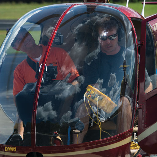
“Aces Systems’ patented Trax optical tracker can be mounted inside the cockpit, which allows the technician to make any necessary adjustments on the tracker in-flight,” Underwood said. “It measures the time that the blade is in the ‘cone’ which extends up from the cockpit and then compares that to the information on the other blade or blades in the same cone. The higher the blade, the longer the time spent in the cone and the lower the blade the shorter the time.”
“Now the digital analyzer is doing the blade tracking electronically and not relying on the human eye. It gives you a lot more consistency and accuracy,” he said. “The biggest limitation to this technology is you can’t do it at night with most units. The ones with night time tracking capability are very expensive. But, the new automated units are faster, easier and much more accurate.”
